Overview
Tracks in the Pacific Electric were of two types: tracks not in streets and tracks in streets. Tracks not in streets are tracks on a private right-of-way. For example, here is a PE car on the Northern District’s four-track mainline:
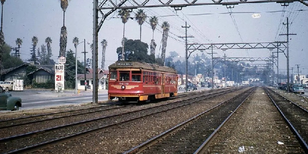
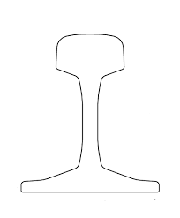
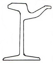
The rail used on private right-of-ways is called T-rail. The rail has a wide foot to allow it to sit firmly on wood ties. Spikes hold the rail to the tie. A cross-section of this rail looks like this:
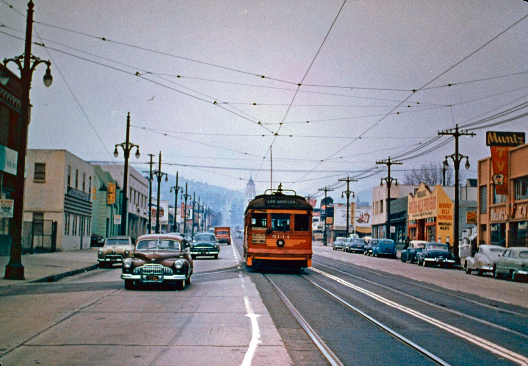
Here is an example of tracks in streets, the car is on Highland Ave in Hollywood:
The rail used in streets is called girder-rail. A cross-section of this rail looks like this:
Girder-rail has a projection on the inside to provide a clear path for wheel flanges in the street’s asphalt. Girder rail is assembled just like T-rail but in a trench cut in the street, then asphalt is poured in the trench up to the top of the rail to form a more-or-less flat roadway for autos.
T-Rail Assembly Detail
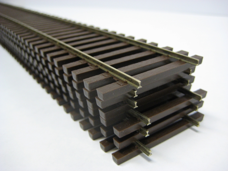
Here is a photo of a section of model railroad T-rail track that matches the prototype:

In the photo can be seen the roadbed at the bottom, wood ties on top of the roadbed, tie plates on top of the ties (the small white things), 33′ (8.25″ at scale) lengths of rail on top of the tie plates, spikes through the tie plates holding the rail to the ties and finally, rail joiners (other white things) holding the ends of the rail sections together. Also, note that the rail joints are staggered like the prototype. The prototype staggers the rail joints to improve the comfort of the train ride. The tie plates, rail joiners and sides of the rail will be painted an iron rust color and ballast (gravel) added to cover the roadbed to complete the representation of the prototype.
A good portion of my layout will need to be built with T-rail. When asking if I have any of the streetcars running, consider that the track is very complicated and will require some time to build.
2024-01-25
I don’t know what’s the most common method of laying down T-rail track. I suspect laying down “flex track” is most popular. Here is a picture of flex track from Right O’ Way:

With flex track, vast amounts of track can be laid down quickly. It’s easily bent for curves. It’s already properly gauged. It’s easy to make progress on the layout. Unfortunately for me, flex track isn’t available in every tie size (L x W x H); ties are different from railroad to railroad. Or available in every rail size; prototpe rail comes in all kinds of sizes. Also, the track isn’t assembled from prototypical rail lengths (like 33′) so there are also no rail joiners. So, flex track is not an option for me.
Which brings up the question of, “Why bother with details?” My friend Bob has said that a model railroad is really only an impression of the real thing. I know he’s right. If a modeler is willing to build with what’s available it makes the task so much easier. Then, why not get wooden trains from a toy store and use them? Obviously, the level of detail is what the modeler desires and is willing to work to achieve. If I’m going for Proto:48 then I’m in for a lot of struggle.
While I keep an eye out for commercially available parts I can use, I am resigned that I must have many things fabricated and assembled by hand. Take rails, for example. Model rail comes in 3′ lengths. The expectation is that the modeler will install the rail in one long piece. I will need to cut the 3′ length into 8.25″ sections. Tie plates and spikes I think I can buy. But Pacific Electric ties are 8 feet long by 8″ wide by 6″ high. This doesn’t seem to be available to buy. I will need to have them fabricated. I may need between 10,000 and 20,000 pieces. Yes, the thought of that many ties makes me want to rethink the whole layout plan.
I will note that prototype railroads needs ties spaced about every 20″ in order to hold gauge and support the weight of the train. A model railroad doesn’t really require this number of ties but are included so the track looks right.
Then comes the question of how to assemble so many components so that the track is at the precise gauge and is straight or curves nicely. An idea I really like (but is unusable as-is) is a track assembly fixture from Fast Tracks:
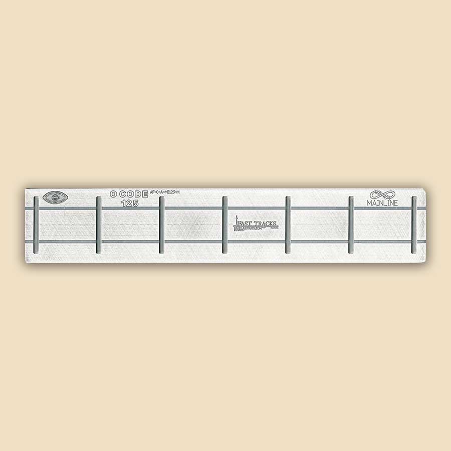
The fixture is unusable, unfortunately, because it’s for O-scale, not Proto:48 (track gauge too wide); it requires a few Printed Circuit Board (PCB), not wood ties (vertical slots) to hold the rails (horizontal slots) at gauge and it’s for Code 125 rail (0.125″ high) and I want Code 100. In between the few PCB ties the modeler would insert regular wood ties. I fear there will be an appearance difference. And the rails are to be soldered to the PCB ties which prevent the use of tie plates.
However, a fixture like this should work great for Girder-rail where PCB ties will be hidden under the street and tie plates and spikes are not needed. The smaller number of PCB ties is perfectly adequate for streets to hold rails at gauge. I’ve had a fixture fabricated to see if it’s usable and will describe it in the next section. But for T-rail, I would like some kind of fixture to ease assembly and ensure accuracy. This will require some thought.
2026-06-26
The compromise: with all the R&D to be done and amount of track to be laid, I convinced myself that some kind of compromise between true detail and detail impression was going to be needed. I will lay track in 3′ sections that track comes in and stick plastic rail joiners on the rail sides if I ever get time for it.
I also have started printing ties on my 3D resin printer that are Pacific Electric size and have the tie plates in the correct position. Thus, when I go to spike down rails they will fall into the correct gauge. Experiments in track laying have shown this scheme works very well.
I was a little bothered by the smoothness of the ties from the printer and thought I would just have to get along without wood grain detail. Then the Google AI pointed out that the printer slicer could add grain detail. One more thing to test out.
Girder-Rail Assembly Detail
TBD

Leave a comment