But First, the Time Frame
Some history.
The Pacific Electric as I’ve shown in a map earlier came into being in 1911 with the Great Merger. It ceased as a passenger carrier in 1961. The Western District of the Pacific Electric, which I’d decided to model, had been before 1911, the Los Angeles Pacific Railway. As I’ve said before, the District is too large to model as of 1911.
The District remained relatively intact until 1940. Note that the flood of 1938 caused the San Fernando Valley lines to Canoga Park and San Fernando to be abandoned past North Sherman Way. A little piece of the San Fernando line did survive in San Fernando for a number of years to service the orange packing houses. The Sepulveda Dam, seen in numerous movie and TV films was built as a result of the flood.
But 1940 was a bad year for the Pacific Electric and Los Angeles mass transit but good for helping to simplify the Western District. The Western and Franklin Line closed as well as the San Vicente Blvd line in Santa Monica, the Beverly Hills via San Vicente Blvd and the Playa del Rey and beach cities lines.
On the other hand, 1940 was when the Cahuenga Parkway was built. This would be a great thing to model. Before this time, the Pacific Electric ran through the Cahuenga Pass on private right of way with Cahuenga Blvd off to one side. With the building of the Parkway, the tracks ended up in the center of the Parkway. Great coexistence. And courtesy of Caltrans, I have plans for much of the roadway detail.
So I decided to model the Western District as of about 1940, give or take. Here is my estimation of the Western District about 1940.

Most Model Railroad Plans
Most model railroads I have seen have a design for the tracks that is roughly just a straight line:

To fit the design to a room and get the most distance from Terminal to Terminal, the design gets stretched and bent:

The benchwork supporting the tracks cannot be one solid mass filling the room. Aisles have to be left to allow reaching all parts of the track for construction, viewing and maintenance. The benchwork supporting the track thus runs along three walls and down the center as a peninsula in this example. Benchwork can’t be too wide else the track and scenery are not reachable from the aisles.
My Model Railroad Plan
The goal of my model railroad brings several complications to any plan. First, there is a big loop from Los Angeles through Hollywood, Santa Monica, Venice, Culver City and finally back to LA. It’s not a straight line. Second, my railroad is streetcar lines. There’s trolley wire up over the tracks everywhere.
A loop of track prevents getting to the inside unless you duck under the track or a section of track lifts out or swings to the side. Duck-unders are hard on old guys like me. Track-moving methods require interlocking to keep a train from running into the gap. Even on non-streetcar layouts, these access methods are inconvenient. But add the consideration of trolley wire and they’re really problematic. Trolley wire is contiguous so that the trolley pole can follow the wire.
If the loop is squished to look like a flattened rubber band on edge, then the aisle must be around the outside. This reduces room space utilization. The layout will be much smaller. My layout has the additional problem of my desire to model a portion of downtown Los Angeles.
LA streets are arranged in a typical grid pattern. If you think about a block, it’s surrounded on all sides by streets. Each block is like a loop, it’s hard to get to the inside for maintenance without ducking under and streets just can’t be moved even if there was a place to move them to. And don’t forget the trolley wire problem.
What to do? Then I had another crazy idea. Raise the layout from the normal 3-4 feet above the floor to six feet above. Except for layout legs, I could walk anywhere under the layout without bending over. Then use a step-stool to get up to the track level. The additional advantage is I could add straight-ish tracks at three feet around the outside of the barn’s 2nd floor. And by restricting the grid portion of the layout to the center of the room I could also add straight-ish tracks at six feet around the outside of the 2nd floor.
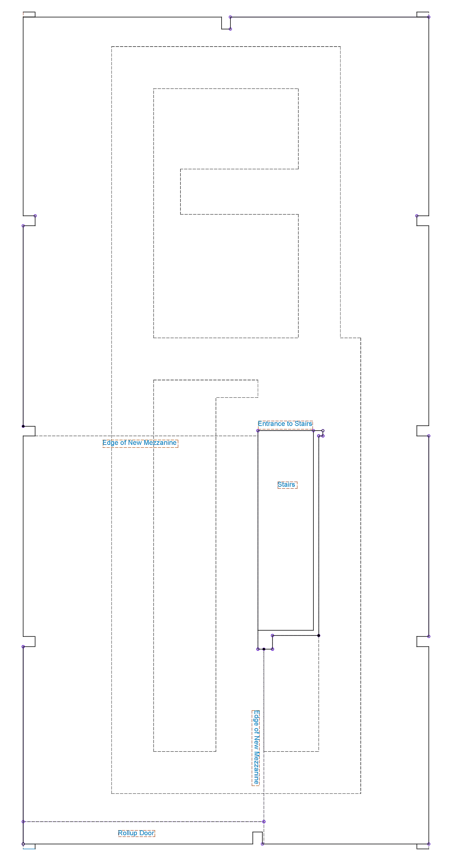
So here’s a diagram of the empty 2nd floor:

The area bounded by the left wall, the rollup door and the dotted lines marked “Edge of New Mezzanine” is where the two adjustable mezzanines were added to fill out the as-built 2nd floor. Note that the stairs are towards the center of the room which complicated the layout plan.
After a LOT of reworking the plan, here’s the aisle plan for the 2nd floor:
The aisle plan will make more sense when view with the six foot level track plan:

The CAD package I use, Fusion 360, is not very good at line drawings. Dashed lines generally indicate edges of benchwork and center lines, edges of streets. Solid lines are mostly the desired paths for the tracks, representing mostly double tracks that allow streetcars to travel in opposite directions.
The notable features of this level are the Hill St Station, the Subway Terminal, Angels Flight, Hill St Tunnel #1, Hill St Tunnel #2, the Echo Park Line, the Hollywood Line, the six-foot level of the Elevator and the Burbank/Glendale line.
Here is the three foot level track plan:
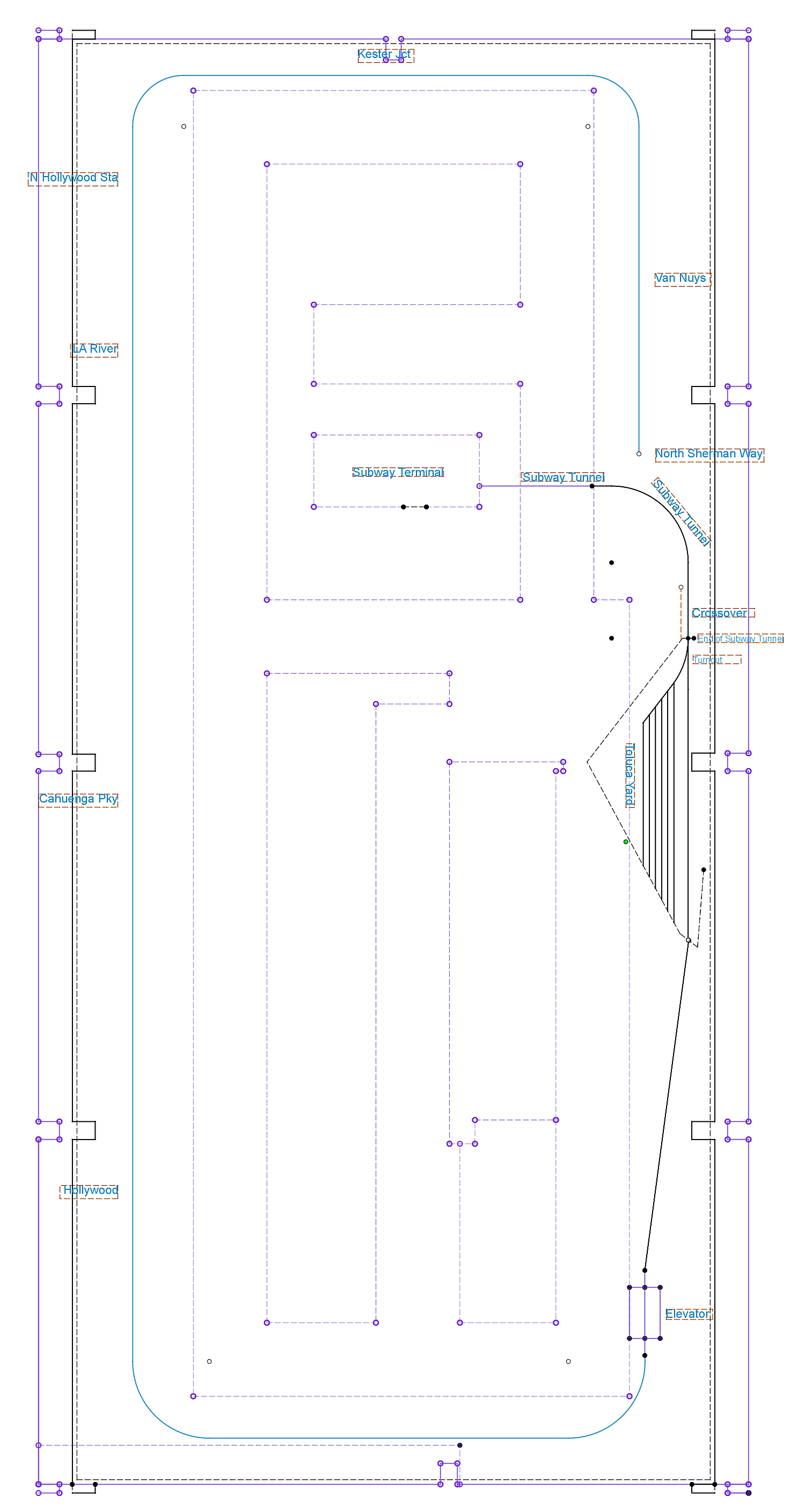
The notable features of this level are the Subway Terminal, the Subway Tunnel, the Toluca Yard, the three-foot level of the Elevator and the San Fernando Valley line.

Leave a comment